
Robot power architecture
Architecture overviewBattery input
Robot Power Hub
Input protection · Power distribution · Monitoring
- Motor domainMotor loads
- Compute domainCompute units
- Sensor domainSensors
Power distribution, monitoring, and interfaces
- Battery input protection
- Design for reverse polarity, surges, and short circuits. Check input requirements against battery characteristics and system loads.
- Three dedicated load domains
- Account for startup and acceleration peaks in the motor domain, power-up stability in the compute domain, and power noise and fault detection in the sensor domain.
- Power telemetry
- Monitor input and output voltage, current, temperature, and fault states to help locate faults on the input or load side.
- CAN and ROS 2 integration
- Connect to the robot controller over CAN and expose power and fault information to ROS 2 for diagnostics and shutdown logic.
Typical use cases
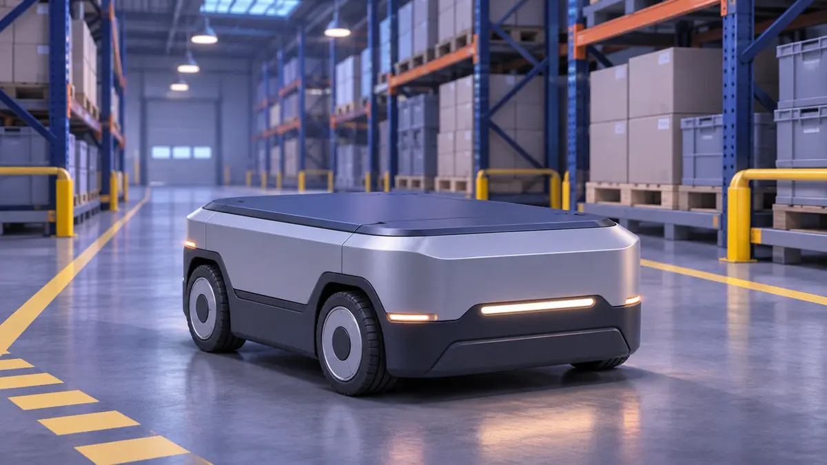
Frequent starts and stops
Chassis motors draw varying current during startup, turning, and acceleration. Separate domains make it easier to verify stable power for compute units and sensors during integration.
Concurrent compute and sensing
When vision, ranging, and compute run concurrently, evaluate supply stability, noise, and sustained consumption for each load type.
Prototype debugging and fault isolation
If the robot restarts or a sensor goes offline, use input status, output load, and fault data to narrow down voltage drop, overload, or heating.
System integration considerations
- Peak and continuous loads
- Check battery supply conditions, continuous and peak demands, and combined startup loads. Verify power headroom under representative conditions.
- EMC and temperature rise
- Evaluate motor interference, wiring, enclosure cooling, and sustained temperature rise together. Check interactions between power, communications, and sensing equipment.
- Interfaces and fault handling
- Confirm power requirements, available telemetry, and fault reporting so the main controller can incorporate power events into system alarms and responses.